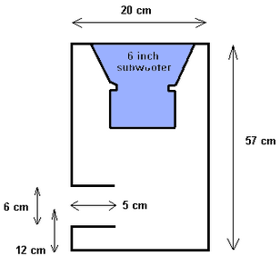
Simple Design Subwoofer Box

0 comments
Boxes are made not based on theoretical , but using the "feeling" that I was the proper size. box if you want a more orderly manner, please use the guide and the calculation of the size of the subwoofer box making a widely circulated on the internet. I took the box with the type of box design for the simple reason ventilated and easy to make. specification of the box that I created can be seen in the picture.

The following are the measures that exist in design subwoofer box :

Simple


This box design is not in the specialize for use in cars, such a box is just perfect for a home audio system that is usually used for DVD media player, computer, or game console. subwoofer box actually has a variety of good design for car audio, active speakers, multimedia, and home theater
Continue reading[...]

Basic Theory IC 555

0 comments
Theory Timer 555
Timer 555 is a timer IC that works based on the RC circuit and the comparator is coupled with a digital component (R-Sflip-flop). The first 555 of the type manufactured by Signetics SE-555 working at -55 ° C to 125 ° C and the NE-555 working at 0 ° C-70 ° C. Then 555 is produced with different designs include the LM555, 556 (dual version), and LMC-555 (CMOS version). Timer 555 operates at +5 V dc power supply sd +18 V with temperature stability of 50ppm / ° C (0.005% / ° C). Output 555 can be a current sink / source up to 200mA. IC 555 is compatible with the components of TTL, CMOS op-amps, transistors and other types of linear ICs.

Basic

Timer 555 can operate either as a monostable or astable. The resulting square wave output can have a variation of duty cycle ranging from 50 - 99.9% and the frequency of less than 0.1 Hz up to more than 100KHz. 555 Series consists of two voltage comparators (COMP1 and COMP2), a control flip-flop RS (reset / set) that can be reset from outside via the pin 4, an inverting amplifier output (A1), and a discharge transistor (Q1). Kompartor second bias level determined by voltage divider resistors (Ra, Rb, and Rc) contained between Vcc and ground. Inverting input 2/3Vcc komparator1 given input and noninverting input from the given input komparator2 1/3Vcc. Monostable operation requires the input pulse triggers the PIN2 of IC 555. Input trigger voltage drop of more than +2 / 3Vcc toward the voltage is less than + Vcc / 3.

Monostable operation Timer 555
Monostable multivibrator (MMV), also called a one shot, producing a pulse output with a certain period when triggered by a pulse input. Output from Oneshot will instantly go high following the trigger pulse (trigger) and will remain high in accordance with its period. When the period had expired, the output will return low. Outpt Oneshot will remain low until there is another trigger. IC 555 can be operated as MMV by adding an appropriate external circuit.

Both internal comparator prasikap given voltage with a certain voltage level by voltage divider arranged series (Ra, Rb, Rc). Inverting input voltage up to 2/3Vcc komparator1 given, and the noninverting input voltage komparator2 given Vcc / 3. Tersebutlah voltage operation resulted in 555 both as a monostable or astable. External timing circuit (R1C1) connected between Vcc and noninverting input komparator1 through pin6. Pin7 also been linked with causing connected as pin6 transistor to the capacitor C1. When the transistor is on, the resistance of the capacitor is so low that connect (short) through the relationship of CE transistor.

When 555 is connected to the source voltage, input voltage inverting komparator1 will receive registration 2/3Vcc and noninverting input voltage komparator2 would have amounted to Vcc / 3. This causes the RS flip-flop in a reset condition, so that its output Qnot high. Therefore flip-flop connected to the output through an inverting amplifier pin3 (A1) then the output 555 low. In these conditions the capacitor charge (charging). Qnot in the high cause transistor Q1 saturated, which means is connected to ground through a capacitor C1. So in this condition the capacitor to remove the charge (discharge) so that Vc = 0.

If PIN2 give trigger input, when pulsatrigger move towards less than 1/3Vcc voltage as shown in the picture, the noninverting input is more positive than the input komparator2 the inverter , so that the output komparator2 be high. At that time, FIP-flop in the set, so that the output Qnot her low and keuaran 555 high. Because of its low Qnot output, means of transistors in the off. Current flows from Vcc to ground through a capacitor C1. In other words, the capacitor re-charging. (Picture). Capacitor voltage will continue to rise until it reaches 2/3Vcc, at which time the output Vc = 2/3Vcc komparator1 be high and cause the flip-flop is reset and the output 555 back to low. The output 555 will remain until there is another trigger input.

All IC timers rely on an external capacitor to determine the interval of time off-on pulse output. The capacitor would require a certain time to charge or discharge through a resistor. Time can be explained and calculated from the resistance and capacity are given. Equation pulse period to 555 depending on the time required by the capacitor at the time of filling until it reaches 2/3Vcc voltage provided by the RC time constant. Thus, if the capacitor voltage e = E (1 - (-t/RC)), can be calculated time will enable the comparator threshold.
Continue reading[...]

10Hz 60Mhz Frequency Meter

0 comments
The frequency meter can be used to measure the frequency of 10 Hz-60Mhz. The frequency meter has a level of precision or resolution of 10Hz. The frequency meter can be used to measure the frequency of the oscillator, transmitter, frequency generator, cristal, and others during the working frequency trsebut devices in the range 10 Hz - 60MHz. Circuit frequency meter using PIC 16F628A dibagun and with the viewer of the LCD 16 × 2. Frequency meter circuit is working with the working frequency of 4MHz crystal. The series is an electronic frequency meter is quite simple to make. The following picture of the frequency meter circuit.

10Hz

The series of frequency meters above basically works with the source voltage 5VDC. In this series of 7805 voltage regulator has been installed, so it can be operated with a voltage of 5 - 15VDC.
Continue reading[...]

Microcontroller to RS 485 circuit

0 comments
Microcontroller to RS-485 circuit | RS-485 bus can carry up to 256 transceiver modules and over long distances . This is a circuit for connect microcontroller with Rs-485 bus.
Max485
Max485 are low-power transceivers for RS-485 and RS-422 communication. Each part contains one driver and one receiver. Line Length vs. Data Rate The RS-485/RS-422 standard covers line lengths up to 4000 feet. For line lengths greater than 4000 feet, see Typical Applications The MAX481, MAX483, MAX485, MAX487–MAX491, and MAX1487 transceivers are designed for bidirectional data communications on multipoint bus transmission lines.

Microcontroller to RS-485 circuit diagrams
Features
- In μMAX Package: Smallest 8-Pin SO
- Slew-Rate Limited for Error-Free Data Transmission
- 0.1μA Low-Current Shutdown Mode
- Low Quiescent Current
- -7V to +12V Common-Mode Input Voltage Range
- Three-State Outputs
- 30ns Propagation Delays, 5ns Skew
- Full-Duplex and Half-Duplex Versions Available
- Operate from a Single 5V Supply
- Allows up to 128 Transceivers on the Bus
- Current- Limiting and Thermal Shutdown for Driver Overload
Continue reading[...]

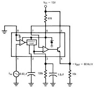
Frequency to Voltage Converter Circuit

0 comments
IC LM2917 Frequency to Voltage Converter
IC LM2917 IC chip is designed specifically as a Frequency to Voltage Converter or Frequency to Voltage converter. In its use to applications Frequency to Voltage Converter IC LM2917 requires few external components. 
There are several examples of applications of Frequency to Voltage Converter IC LM2917 datasheet that is included in the LM2917 IC. In this article series Frequency to Voltage Converter IC also taken from the LM2917 datasheet. The advantages of single chip LM2917 Frequency to Voltage Converter is able to provide instantaneous volt output o at time of frequency change 0 Hz. Very easy to apply in measuring the output frequency with the formulation of single-chip Frequency to Voltage Converter VOUT = FIN x VCC x R1 x C1.

Then the single-chip LM2917 Frequency to Voltage Converter This configuration requires only the RC only in frequency doubling. And has an internal zener regulator to aimlessly accuracy and stability in frequency-to-voltage conversion process.

Application circuit Figure IC LM2917 as Frequency to Voltage Converter

Feature-owned single-chip LM2917 Frequency to Voltage Converter
Reference to ground directly with variable reluctance
Op Amp / Comparator with transistor output
50 mA maximum output currents for application directly to the load
Frequency doubling for low ripel
Buid in zener
Linear output ± 0.3%
Application single chip LM2917 Frequency to Voltage Converter
Frequency to Voltage Converter
Rotation speed sensor applications
Speedometer
Tachometer
Cruise Control
Cluth Control
And other applications associated with the measurement of rotation speed or frequency measurements.
Continue reading[...]

How Regulator with 2 Photocoupler

0 comments
Working of Regulator with 2 Photocoupler that is :
  • Photocoupler N901 - used as a coupling-off control on the regulator by mikrokontrol. Which is set high and low voltage B + (st-by at the B + voltage is low). Control of the pin-37 POWER mikrokontrol → V610 → VD913 V908 → N901.
  • Photocoupler N903 - used to control on-off the regulator of X-ray circuit protector. X-ray protector circuit of flyback → VD451 → VD452 → SCR VS472. If the flyback voltage regulator over the job will automatically be turned off by N903
  • To disable the X-ray circuit protector, it can be temporarily removed photocoupler N903 first. In normal conditions the voltage at the transistor V474 should be zero.

Regulator Schematics
Trobelshuting there is no voltage for 5v st-by on the secondary :

  1. Disable by removing the first circuit protectors N903
  2. Check the voltage of 300V
  3. Check all transistors
  4. Check the start voltage of 300V by R909 >> R906 to the base of transistor power regulator
  5. Check the feedback C910 >> R904 (to oscillate)
Continue reading[...]

Simple Circuit 12V to 120V DC DC Converter

0 comments
Its a simple circuit of 12V DC to 120V DC converter. The circuit consists of two phases first phase of the investor base and then a rectifier and filter stage. IC1 NE555 is wired as an astable multivibrator operating at a frequency of 100 Hz and can be adjusted to the preset R1. IC1 output is coupled to the clock input of IC2 is a dual CMOS D flip-flop. IC2 divides the pulse train of 100 Hz IC1 2 50 Hz pulse trains that are 180 degrees out of the party and offered on the pin 1 and 2 of IC2.

When pin 1 is high transistor Q1 conducts and current flows through the upper half of T1 primary winding. When pin 2 is the transistor Q2 conducts and high current flows through the lower half of the primary coil T1. As a result of a voltage of 120 V AC are induced in the secondary of T1. This voltage is rectified with bridge D1 to provide a 120V DC output. Capacitor C2 is the DC input filter, while C3, C4 are the output filters.

Notes.
  • The circuit can be assembled on a vero board.
  • Q1 and Q2 require heat sink.
  • Output power of this dc dc converter is around 100 watts.
  • IC1 and IC2 are to be mounted on holders.
  • An optional 5A fuse can be added in series to the 12V supply line.
  • T1 can be a 9-0-9V /250V/3A mains transformer.
  • If 3A bridge is not available make one using 1N5408 diodes.
  • Out of the two Flip-Flops inside CD4013 only one is used here.
  • Output of IC1 must be set to 100Hz by adjusting preset R1
Continue reading[...]

12 Volt Charger Circuit with LM350

0 comments
The strength supply routine structure is developed as a resource of continuous present with adverse heat range coefficient. Transistor Q1 (BD 140) is used as a heat range indicator. transistor Q2 is used to avoid the strength supply from discharging through R1 when strength is out of stock. Getting routine is developed depending on the LM350 present regulator IC. The result present of the battery charger can be altered between 13-15 V by various the POT R6.


LM350 will try to keep the present decrease between the feedback pin and result pin at a continuous value of 1.25V. So there will be a continuous present circulation through resistor R1. Q1 act here as a heat range indicator with the help of R6/R3/R4 elements that are more or less manages the platform present of Q1. As relationship emitter / platform of transistor Q1, the same as other semiconductors, containing the heat range coefficient of-2mV / ° C, the present result will also display a bad heat range coefficient. This one is just a aspect of 4 huge, because the difference of the emitter / platform of Q1 is increased by a aspect of category P1/R3/R4. This causes some-8mV / ° C. LED will lighting whenever strength is available.
Continue reading[...]

Vertical IC PIN OUT DATA

0 comments
Vertical Vin = input (non-inverted), Vout = Vertical output, VfB = Vertical feedback (inverted inpput)
Vcc to pump-up can be traced through the diode PUM-up and pump up Elco Capacitor
VfB = or to Vin2
= Gnd or Vcc (-)


Vertical IC PIN-OUT DATA
AN5521 Vin = 4, Vout = 2, Vcc = 7, Gnd = 1, VfB =
AN5522 Vin = 7, Vout = 5, Vcc = 2, Gnd = 4, VfB = 1
AN5539 Vin = 4, Vout = 2, Vcc = 6, Gnd = 1, VfB = 5
AN15525 Vin = 7, Vout = 5, Vcc = 2, Gnd = 4, VfB = 1

LA7832 Vin = 4, Vout +2, Vcc = 6, Gnd = 1, VfB = 5
LA7835 = 2 Vin, Vout = 11, Vcc1 = 1, Vcc2 = 7,
LA7837 = 2 Vin, Vout = 12, Vcc1 = 1, Vcc2 = 8, Gnd = 11, VfB = 7
LA7838 = LA7837
LA7840 Vin = 4, Vout = 2, Vcc = 6, Gnd = 1, VfB = 5
LA7841 = LA7840
LA7845 = LA7840
LA7846 = 5 Vin, Vout = 3, Vcc = 7, Gnd = 2, VfB = 6
LA7848 Vina = 5, VinB = 6, Vout = 3, Vcc (+) = 7, Vcc (-) = 2
LA7876 Vina = 5, VinB = 6 Vcc (+) = 7, Vcc (-) = 2

STV9302 = see AN5522
STV9379 = See AN5522


TA8403 Vin = 4, Vout = 2, Vcc = 6, Vcc = 6,
TA8445 Vin = 2, Vout = 11, Vcc1 = 1 (9v), Vcc2 = 7 (26v), Gnd = 10, 50/60 =

TDA1771 Vin = 3, Vout = 1, Vcc = 9. Gnd = 5
TDA4865 Vin = 6, Vout = 5, Vcc = 1, Gnd = 4, VfB = 2
TDA8175 Vin = 7, Vout = 5, Vcc = 2, VfB = 1
TDA3653 Vin1 = 1, Vin2 = 3, Vcc1 = 9, Vcc2 = 6, Vou = 5, Gnd = 4
TDA8350 Vina = 1, VinB = 2, VoutA = 10, VoutB =, Vcc1 = 3, Vcc2 = 9, Ewin = 12, Ewout = 11
See tda8357 TDA8351 =
See TDA8357 TDA8356 =
TDA8357 Vina = 1, VinB = 2, VoutA = 7, VoutB = 4, Vcc1 = 3 (12v), Vcc2 = 6 (45V), Gnd = 5
TDA8358 Vina = 1, VinB = 2, Vcc1 = 3 (12v), Vcc2 = 9 (25V), VoutA = 4, VoutB = 10, Gnd = 6.7, Ewin = 5, Ewout = 8
TDA9302 = see LA78040
Continue reading[...]

Solar tracker With AT89S52

0 comments
AT89S52 With solar tracker is a tool used to control the direction of the panel Solar Cell for always getting sunlight. AT89S52 With solar tracker uses a light sensor as a light detector. AT89S52 With solar tracker uses dc motors for Solar Cell panels menegendalikan direction. Broadly speaking AT89S52 With Solar tracker may be analogous as a tool to adjust the position of the exposure to the sun solar cell  direction by Ensor sensing light and a DC motor which is controlled using a microcontroller AT89S52.

Solar tracker With AT89S52

Solar


Pictured above is a series that could be used for the light sensor on the solar tracker With AT89S52. The light sensor on AT89S52 With Solar tracker can use the LDR. Configuring LDR on Solar Tracker With AT89S52 using OP-Amp as a signal conditioner output of the LDR.
Continue reading[...]

Timer with about 10 minutes

0 comments
Applications of 555 timer IC is very diverse, one series of 10 Minute Timer with IC 555. 10 Minute Timer This circuit uses IC NE555 is set as a monostable multivibrator. The timing of the timer circuit 10 minutes with the IC 555 is governed by the configuration of C2, R4 and R5. The greater the value of C2 at 10-minute timer circuit with IC 555 timer is active then the time will stay longer. 

Total resistance value between R4 and R5 also determine the active circuit 10 minute timer with IC 555, where the greater the value the longer time was also active. The core active setting the timer on the set of C2 charging time for 10 minutes on the timer circuit with IC 555. So, with the value of C2 remain so with time on the circuit timing Timer 10 minutes by IC 555 can be set by changing the resistance value R 4 + R 5. Indicators of active timer at 10 minute timer circuit with IC 555 uses the LED D2 and D3 will light up only one course to identify the active timer and the timer has not been met.


Figure 10 Minute Timer circuit with IC 555


Description:

S1 is used to set / reset timer
R5 is used to set the timer to the desired time
Continue reading[...]

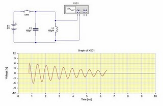
Basic Principles of the LC resonance circuit

0 comments
If so far you are still confused how the actual origin of the resonance between the capacitor and the inductor is in progress, then the simple circuit above will answer your confusion.


Basic

By understanding a simple electrical circuit above hopefully we will be able to understand the working principle of a series of more complicated and complex that uses the relationship as a series inductor and capacitors transmitter and receiver.

Note the picture above, when the switch SW1 is pressed and released back then obtained by the same signal as in the picture above signal. Initially when SW1 is connected to the voltage supply, the capacitor will make filling fast. Then when SW1 is released charge on the capacitor will be used by the inductor as the supply voltage. In accordance with the general nature of the inductor that the DC signal will be considered ordinary wire inductor such that current flowing quickly through the inductor and the charge on the capacitor decreases rapidly exhausted. Uniquely current that was flowing through the inductor and capacitor will fill the empty capacitor back through the other terminal (negative cycle). Charging kapasior place quickly, then inductor will burden the back so that emptying of cargo going back. That so happens repeatedly (resonance occurs between L and C) until the electrical charge had been used up by these two components in the form of power losses. Equations between regular wire inductor is the inductor with wire work as usual at the time of current flowing to him. Inductors But unlike ordinary wire when current flows to him and vice versa. So it will not happen short circuit if the inductor to get the supply voltage alternating current (AC). But in ordinary wire short circuit will still occur even if the voltage of alternating current.

From the above analysis we can conclude that the LC resonance occurs because one component part affected by the characteristics of other components. For frequencies generated depend on the value of L and C itself. The greater the value of both the frequency will be smaller and smaller the value of both the frequency value will be even greater.
Continue reading[...]

LM350 12 Volt Battery Charger

0 comments
The battery circuit scheme is designed as a source of constant voltage with negative temperature coefficient. Transistor Q1 (BD 140) is used as a temperature sensor. transistor Q2 is used to prevent the battery from discharging through R1 when electrical power is unavailable. Charging circuit is designed based on the LM350 voltage regulator IC. The output voltage of the charger can be adjusted between 13-15 V by varying the POT R6.


LM350 will try to keep the voltage drop between the input pin and output pin at a constant value of 1.25V. So there will be a constant current flow through resistor R1. Q1 act here as a temperature sensor with the help of R6/R3/R4 components that are more or less controls the base current of Q1. As connection emitter / base of transistor Q1, the same as other semiconductors, containing the temperature coefficient of-2mV / ° C, the voltage output will also show a negative temperature coefficient. This one is just a factor of 4 large, because the variation of the emitter / base of Q1 is multiplied by a factor of division P1/R3/R4. This leads to some-8mV / ° C. LED will light whenever power is available.
Continue reading[...]

Drive Stepper Motor with IC UCN5804

0 comments
IC IC UCN5804 is designed specifically for the purpose of stepper motor drivers. Stepper motor driver IC UCN5804 with this very simple and uses only 2 additional components as current-limiting resistors which flows into the stepper motor, it also can be removed so that the stepper motor driver is a pure IC UCN5804 only use only. UCN5804 IC can be used for stepper motor driver with 5-20VDC voltage. Source voltage required for a series of stepper motor driver IC dengn this UCN5804 follow steppernya motor voltage. Picture a series of stepper motor driver ICs with UCN5804 in detail can be seen in the following figure.

Drive Stepper Motor circuit UCN5804

Drive

In the series of stepper motor drivers with IC UCN5804 above to run a DC motor takes 2 inputs ie, the input signal and the input logic stepper direction of rotation. The input signal is a pulse stepper with a certain frequency where the frequency of these pulses that determines the speed of stepper motor puter. Then the input logic is a stepper motor rotating direction input logic 0 and 1 that is given to the IC UCN5804 to adjust the stepper motor rotating direction.
Continue reading[...]

Voltage to frequency converters LM231 LM331

0 comments
The LM231/LM331 family of voltage-to-frequency converters are ideally suited for use in simple low-cost circuits for analog-to-digital conversion, precision frequency-to-voltage conversion, long-term integration, linear frequency modulation or demodulation, and many other functions
Voltage-to-frequency converters LM231/LM331
Features Voltage-to-frequency converters LM231/LM331:
- Guaranteed linearity 0.01% max
- Improved performance in existing voltage-to-frequency
conversion applications
- Split or single supply operation
- Operates on single 5V supply
- Pulse output compatible with all logic forms
- Excellent temperature stability, ±50 ppm/°C max
- Low power dissipation, 15 mW typical at 5V
- Wide dynamic range, 100 dB min at 10 kHz full scale
- Wide range of full scale frequency, 1 Hz to 100 kHz
- Low cost
Continue reading[...]

Characteristic NiCad Battery Charger

0 comments
The advantages of NiCad batteries are rechargeable and can be in physical shape with regular batteries so no need to modify its casing. In addition, if compared with NiCad Batteries ordinary batteries, nickel cadmium batteries, or better known as NiCad batteries, the resistance has on ordinary batteries (NiCad battery with a record of the condition is still good). NiCad batteries in the market today there are several options for its size, among other 700mAh NiCad battery or 1500 mAh.
Characteristic
The point is that these NiCad battery can supply current to the electronics equipment with current 700mA for 1 hour (for 700mAh battery). So if we use these 700mAh NiCad batteries for electronic devices that draw a current of 1 A, the NiCad battery can only last for less than 1 hour. The temperature of NiCad batteries also affect battery life. If the battery is too hot the battery will quickly run out due in part generated by the battery current is converted into heat.

Characteristics NiCad Batteries :
1. NiCad batteries must be filled with a large constant current.

2. The battery will be fully charged if it reaches 140% charge of the maximum charging the battery.

3. The variation of the battery voltage changes depending on the charging function and also depends on the temperature of the battery.

4. When charging has been completed then the temperature will rise quickly (heat rises quickly) so chager need to be turned off. Because if not turned off will cause the battery temperature will continue to rise and eventually will explode.
Continue reading[...]

Class A headphone amplifier

0 comments
Class A headphone amplifier
Continue reading[...]

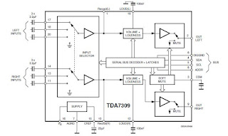
TDA 7309 Digital Audio Processor Circuit

0 comments
Digital Audio Processor TDA 7309 is a stereo audio processor with independent volume control of each channel was to get the audio quality of a good processor. Digital Audio Processor TDA 7309 is equipped with a loudness control is controlled externally. Digital Audio Processor TDA 7309 also has a soft mute feature stand-alone for each canals. Digital Audio Processor TDA 7309 is controlled via the I2C serial bus system with a microcontroller interface.


Block Diagram of Digital Audio Processor TDA 7309Feature-owned Digital Audio Processor TDA 7309The input multiplexer with 3 stereo inputRecording function on the output lineLoudnes external ontrolIndependent volume controlDigital volume control with 1dB stepSoft MuteAll functions of the Digital Audio Processor TDA 7309 is programmed via the I2C serial bus system
Continue reading[...]

USB Battery Charger controller circuit using LM3622

0 comments
From USB Battery Charger controller circuit using LM3622
Continue reading[...]

TDA1308T Headphone amplifier circuit

0 comments
TDA1308T Headphone amplifier circuit 
TDA1308T
TDA1308T Headphone amplifier circuit
Continue reading[...]

555 Timer IC Working Principle

0 comments

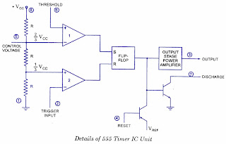
Block Diagram of 555 timer IC:

Comparator 1 has a threshold input (pin 6) and a control input (pin 5). In most applications, the control input is not used, so that the control voltage equals +2/3 VCC. Output of this comparator is applied to set (S) input of the flip-flop. Whenever the threshold voltage exceeds the control voltage, comparator 1 will set the flip-flop and its output is high. A high output from the flip-flop saturates the discharge transistor and discharge the capacitor connected externally to pin 7. The complementary signal out of the flip-flop goes to pin 3, the output. The output available at pin 3 is lowThese conditions will prevail until comparator 2 triggers the flip-flop. Even if the voltage at the threshold input falls below 2/3 VCC, that is comparator 1 cannot cause the flip-flop to change again. It means that the comparator 1 can only force the flip-flop’s output high.
To change the output of flip-flop to lowthe voltage at the trigger input must fall below + 1/3 Vcc. When this occurs, comparator 2 triggers the flip-flop, forcing its output lowThe low output from the flip-flop turns the discharge transistor off and forces the power amplifier to output a high. These conditions will continue independent of the voltage on the trigger input. Comparator 2 can only cause the flip-flop to output low.
From the above discussion it is concluded that for the having low output from the timer 555, the voltage on the threshold input must exceed the control voltage or + 2/3 VCC. They also turn the discharge transistor on. To force the output from the timer high, the voltage on the trigger input must drop below +1/3 VCC. This also turns the discharge transistor off.
A voltage may be applied to the control input to change the levels at which the switching occurs. When not in use, a 0.01 nano Farad capacitor should be connected between pin 5 and ground to prevent noise coupled onto this pin from causing false triggering.
Connecting the reset (pin 4) to a logic low will place a high on the output of flip-flop. The discharge transistor will go on and the power amplifier will output a low. This condition will continue until reset is taken high. This allows synchronization or resetting of the circuit’s operation. When not in use, reset should be tied to +VCC.
Continue reading[...]

11 90 hz Subwoofer Filter Using TL072 Op Amp

0 comments
11-90 hz Subwoofer Filter Using TL072 Op-Amp

The subwoofer clarify ambit allows the accession of subwoofers to an absolute full-range system, alms adjustable low-pass clarification with alternative R6 and R8 addition and mono-summing.

The Subwoofer clarify ambit to abolish for abstracted pre amplifier to drive the low abundance complete a lot. In tone, alarm tone, accustomed Can not be done … is a accomplished abysmal low bass sounds like a bass drum, or at a cine circuitous in a low articulation if we can be heard with But to add cabinets and amps. The subwoofer ambit is canyon low abundance with in 11-90 Hz. Switching ability accumulation 12V cut out if they charge to use +-15V. I had change the Capacitor to cut out vocals per the red amphitheater mark.

Continue reading[...]

Traffic Lights Circuit

0 comments
The circuit of traffic lights in my opinion is a series of easy-hard-easy to make. 


Traffic

Where we are required to be able to condition the flame of three lamps by following the existing traffic regulations. If we use computer programming as a regulator of the third condition of the lights probably we will not spend too much time to make it. As an example with microcontroller programming or programming-based computer applications such as Visual Basic, Delphi and many others. But if you use a common electronic circuit components used may be somewhat time consuming to get the results you are fully in accordance with the conditions of traffic lights that use the streets.

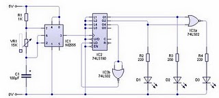
Well ... if youre looking for examples of a series of simple traffic light above the range can I recommend to you. The working principle of a series of traffic light above is very easy to understand. The series of above use the output from IC up / down counter 74 190 as the producer output tercacah and then conditioned using logic gates so that the logic in accordance with the logic of the actual traffic light. Actually you can also use the IC counter ups as pencacahnya. Red lights are represented by the LED D1, D2 and yellow by green led by led D3.

LIST OF COMPONENTS:
Resistors: R1 (1 Kohm), R2, R3 and R4 (220 ohms) and VR1 (Potensio 10 K / 15 K)
Capacitors: C1 (100 UF)
Led: D1 (red), D2 (yellow) and D3 (green).
Integrated Circuit: IC1 (NE 555), IC2 (74LS190) and IC3 (74LS02)

HOW TO WORK AND ANALYSIS OF CIRCUIT LIGHT TRAFFIC:
To generate the signal used peggerak counter circuit astable circuit IC555.
R1, C1 and VR1 is a combination astable as a determinant of the speed of the clock signal to be inserted to the input counter and in the end will determine the length of time the flame of their lamps. The greater the value of the three clock cycles will stay longer and vice versa.
To obtain a combination of LEDs required only 2 bits output from the counter circuit.
Bit-3 from the output to the counter only be used as reset the enumeration.
The lamp was first lit the light yellow color, due to connect with the output Q1 of counter IC. Then followed by a red lamp that is connected to the output Q2. Then both (yellow and red) light simultaneously. The last green light will turn on its own.
The series of bit counter counts up with the sequence:
- 0 1 (light yellow light)
- 1 0 (red light)
- 1 1 (light yellow and red lights)
- 0 0 (light turned green, according to the nature of the gate NOR)
Examples of traffic light sequence apply only to one lane for traffic light circuit that uses more than one line then you can use the same circuit device and use a combination of gates as a liaison between the conditions of each lane. This means you should make a longer red light is illuminated on each other point for point which it operates. These conditions can be achieved by utilizing a combination of logic gates in a chain.
Continue reading[...]

50MW Audio Amplifier circuit

0 comments
50MW Audio Amplifier circuit

The following is a small audio amplifier comparable to what you may come across a small transistor radio medium size. The input stage is biased to ensure that the power is divided equally to provide the two complimentary output transistors which are slightly biased in conduction of the diodes between the bases. A 3.three ohm used in sequence for the use of the issuers of the output transistors to stabilize the bias current that does not change significantly with temperature or several transistors and diodes.

Due to recent increases in bias voltage between the emitter and base decreases as a result of minimizing driving. Input impedance is 500 ohms and the voltage gain is approximately five to eight ohm speaker connected. The voltage swing around the speaker is 2 volts without distorting production and capacity is at the same time in the 50 milliwatt range. A high voltage provided as well as the addition of heat sinks in the output transistors would be a great source of more power. Circuit thirty milliamperes draw a supply of 9 volts.
Continue reading[...]

LED Flasher Circuit Using 555 Timer IC

0 comments
This is a simple LED flasher project that uses a common 555 timer IC for its operation. It is configured as an astable mode which means that its output is a square wave oscillator. Two LEDs are connected to its output in such a way that when one LED is ON, the other LED will turn OFF. 

It uses only 10 simple parts that are easily available at any electronic shops. Capacitor C2 charges exponentially through resistors R1, R2 and the resistance of the trimpot. When C2 has charged to about 2/3 VCC it stops charging and it discharges to about 1/3 VCC through R2 and the trimpot resistance via pin 7. This is the standard operation of a 555 timer. When a Vcc of 5 V to 15 V DC is applied to the circuit, the LED will start to flash.
The frequency of the flashing can be changed by varying the resistance of the potentiometer or trimpot.Parts List The parts list of the simple LED project is as shown below.

Continue reading[...]

Symmetrical Power Supply LM317 337 Variable

0 comments
Symmetrical Power Supply LM317/337 Variable is circuit symmetrical power supply with output voltage output that can be set (adjustment). Circuit of symmetrical power supply LM317/337 variable uses  variable DC regulator LM317 to regulator positive and negative voltage regulator LM37 variable for negative voltage regulator. Symmetrical Power Supply series LM317/337 Variables can be used to provide the source voltage with maximum current 1A.

In the application field can be mounted voltmeters at each point its output to ease in setting the output voltage level circuit Symmetrical Variable Power Supply LM317/337 this.


Click image for full image

Circuit  of symmetrical power supply  LM317/337 variable using input source voltage of 18V AC 18V CT transformer CT. To set a positive voltage level can be done by adjusting the potentiometer 25K at the LM317 regulator and to regulate the negative voltage level carried out by adjusting the potentiometer 25K at the LM337 negative voltage regulator.
Continue reading[...]

AC to DC 90 Watt Switching Adaptor

0 comments
ACAC to DC 90 Watt Switching Adaptor Circuit

AC to DC switching adaptor circuit with best achievement ability of 90W. Switching ability accumulation is congenital application a aerial voltage ability switching regulator IC MC33374 and some added added components. The MC33374 IC is a caked aerial voltage ability switching regulators that are distinctively advised to accomplish anon from a rectified AC band source, and in flyback advocate applications.

The MC33374 switching ability adaptor combines the appropriate advocate functions with a different programmable accompaniment controller. At assorted capricious AC inputs, it is able of confined up to 6 A accepted at 15V achievement voltage. This switching ability adaptor is able of accouterment an achievement ability in balance of 150W with a anchored AC ascribe of 100V, 115V, or 230V, and in balance of 90 W with a capricious AC ascribe that ranges
Continue reading[...]

Ramp Generator With 555 Timer IC

0 comments
We apperceive that if a capacitor is answerable from a voltage antecedent through a resistor, an exponential waveform is produced while charging of a capaci­tor from a connected accepted antecedent produces a ramp. This is the abstraction abaft the circuit. The circuit of a access architect application timer 555 is apparent in figure. Here the resistor of previ­ous circuits is replaced by a PNP transistor that produces a connected charging current.

Charging current produced by PNP constant current source is

iC = Vcc-VE / RE

where VE = R2 / (R1 + R2) * VCC + VBE

When a trigger starts the monostable multivibrator timer 555 as shown in figure, the PNP current source forces a constant charging into the capacitor C. The voltage across the capacitor is, therefore, a ramp as illustrated in the figure. The slope of the ramp is given as
Continue reading[...]

FM Signal Tracker

0 comments
FM Tracker 1.5 Volt [Tracking Transmitter] uses the source voltage of 1-cell battery and 3.7 mA current consumption. FM tracer was prepared using the LM3909 IC and some supporting components. 1.5V FM trackers This will give an indication of revenue sources by providing signals emitted by the LED. When finished assembling FM tracking this 1.5V, then the next step is setting the working frequency of this FM tracker, for the sake of convenience we can use the help of an FM receiver and adjust the working frequency FM Tracer 1.5V (tracking transmitter) denagan how to set C3. Where has acquired an FM frequency trackers 1.5V (tracking transmitter) then the LED will light according to information transmitted by the transmitter as terdengan sound through the FM receiver. FM Tracer 1.5V (tracking transmitter) can use regular 12-inch antenna. Playing and learning electronics that mengasikan, 1.5V FM Tracking (tracking transmitter) is a good project to learn electronics.

Circuit FM Tracker 1.5 V [Tracking transmitter]

FM
FM Signal Tracker

Series Description 1.5 Volt Tracking FM [Tracking Transmitter]
For stability, use a NPO types for C2 & C4.
Tolerance for R1 must be 1 or 2%.
Common frequency range is 87-109Mhz FM.
Email wire used in wire coil is made of hookup 22 ga, such as solid Bell phone wire.
Continue reading[...]

Atmel 89S and AVR Programmer STK200

0 comments
If you are looking for an easy-build and useful programmer for the AT89Sxx, AVR MCU, and tiny AVR, here is my simple circuit. The board is signal compatible with the STK200 parallel programmer.
STK200 Parallel Programmer
Layout PCB
Continue reading[...]

Room Noise Detector

0 comments
Every room has a noise level,you can detect the noise level of your room with noise room detector. You can see the series of noise detector its look like simple circuit and everyone can make it.

This circuit is intended to signal through a flashing LED, more than a fixed threshold, room noise, chosen from three fixed levels, namely 50, 70 and 85 dB. Two op amps provide the necessary gain of the circuit sounds like a pick-up is a miniature electric microphone to drive the LEDs. When SW1 at the top of the circuit off. The power of the second, third and fourth circuit and set the entry threshold is 85, 70 and 50 dB. Current drawing is less than 1 mA with LED off and 12 15 mA when the LED is steady on.

Room Noise Detector Components :


R1____________10K   1/4W Resistor
R2,R3_________22K   1/4W Resistors
R4___________100K   1/4W Resistor
R5,R9,R10_____56K   1/4W Resistors
R6_____________5K6  1/4W Resistor
R7___________560R   1/4W Resistor
R8_____________2K2  1/4W Resistor
R11____________1K   1/4W Resistor
R12___________33K   1/4W Resistor
R13__________330R   1/4W Resistor

C1___________100nF  63V Polyester Capacitor
C2____________10µF  25V Electrolytic Capacitor
C3___________470µF  25V Electrolytic Capacitor
C4____________47µF  25V Electrolytic Capacitor

D1_____________5mm. Red LED

IC1__________LM358  Low Power Dual Op-amp

Q1___________BC327  45V 800mA PNP Transistor

MIC1_________Miniature electret microphone

SW1__________2 poles 4 ways rotary switch

B1___________9V PP3 Battery

Clip for PP3 Battery


Place the small box containing the circuit in the room where you intend to measure noise. The 50 dB setting is provided for controlling noise in the room at night. If the light is constant, and often bright flashes, the room is inadequate and too noisy to sleep. The setting is 70 dB for residences. If this level is often exceeded during the day, your apartment is rather uncomfortable. If the noise is constant, over 85 dB for 8 hours a day, you live in a dangerous environment.
Continue reading[...]

PIC Volt and Amere Meter Circuits

0 comments
Volt meter and ampere meter with PIC can be used to measure voltage and current at the same time. The series of volt meter and ampere meter with PIC uses a PIC16F876A as a data processor voltage and current are measured. This circuit uses a LCD viewer 16 × 2, which is used for displaying data voltage and current measurements. In the article volt meter and ampere meter with PIC is to be discussed is limited to devices faucet only. For more details can be seen from the image sequence volt meter and ampere meter with PIC below.


In the circuit volt meter and ampere meter with PIC above used 3 pieces of buttons for setting Calibration measurement data. The circuit is basically working with the source voltage 5VDC.
Continue reading[...]

FRIDGE DOOR ALARM CIRCUIT

0 comments
This fridge door alarm is using a 3V battery supply should be placed (in a small box) in the fridge near the lamp or close to the opening. With the door closed the photo resistor R2 presents a high resistance (>200K) thus clamping IC1 by holding C1 fully charged across R1 and D1. When a beam of light enters from the opening, or the fridge lamp lights, the photo resistor lowers its resistance (<2k) stopping c1 charging current. therefore ic1, wired as an astable multivibrator, starts oscillating at a very low frequency and after a period of about 24 sec. its output pin (#3) goes high, enabling ic2.

This chip is also wired as an astable multivibrator, driving the Piezo sounder intermittently at about 5 times per second. The alarm is activated for about 17 sec. then stopped for the same time period and the cycle repeats until the fridge door closes.

Important Notes

  • Delay time can be varied changing C1 and/or R3 values.
  • Beeper repetition rate can be varied changing C2 and/or R4 values.
  • Stand-by current drawing: 150µA.
  • Place the circuit near the lamp and take it away when defrosting, to avoid circuit damage due to excessive moisture.
  • Do not put this device in the freezer.


Circuit Diagram


Components List

R1 = 10K 1/4W Resistor
R2 = Photoresistor (any type)
R3 = 2M2 1/4W Resistor
R4 = 1M 1/4W Resistor
C1 = 10µF 25V Electrolytic Capacitor
C2 = 100nF 63V Polyester Capacitor
D1 = 1N4148 75V 150mA Diode
IC1 = 7555 or TS555CN CMos Timer ICs
IC2 = 7555 or TS555CN CMos Timer ICs
BZ1 = Piezo sounder (incorporating 3KHz oscillator)
B1 = 3V Battery (2 x 1.5V AA, AAA or smaller type Cells in series)
Continue reading[...]

GAS LEAK DETECTOR CIRCUIT

0 comments
This is a gas leak detector circuit that detects the leakage of LPG gas and alerts the user through audio-visual indications. The circuit operates off a 9V PP3 battery. Zener diode ZD1 is used to convert 9V into 5V DC to drive the gas sensor module.The gas leakage circuit uses the SEN-1327 gas sensor module from RhydoLABZ. Its output goes high when the gas level reaches or exceeds certain point. A preset in the module is used to set the threshold. Interfacing with the sensor module is done through a 4-pin SIP header.

Pin details of the gas sensor module are shown in Fig. 2. An MQ-6 gas sensor is used in the gas sensor module. The sensor can also be used to detect combustible gases, especially methane.

Circuit Schematic


Whenever there is LPG concentration of 1000 ppm (parts per million) in the area, the OUT pin of the sensor module goes high. This signal drives timer IC 555, which is wired as an astable multivibrator. The multivibrator basically works as a tone generator.

Output pin 3 of IC 555 is connected to LED1 and speaker-driver transistor SL100 through current-limiting resistors R5 and R4, respectively. LED1 glows and the alarm sounds to alert the user of gas leakage. The pitch of the tone can be changed by varying preset VR1. Use a suitable heat-sink for transistor SL100.

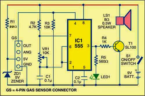
SEN1327 gas sensor pin details


Continue reading[...]

6 WATT Hi Fi AUDIO AMPLIFIER USING TDA2613

0 comments
A 6 watt audio amplifier circuit using TDA2613 is shown here. TDA2613 is an integrated Hi-Fi  audio amplifierIC from Philips Semiconductors. The IC is switch ON / switch OFF click proof, short circuit proof, thermally protected and is available in 9 pin single in line plastic package.
In the given circuit, TDA2613 is wired to operate from a single supply. Capacitor C4 is the input DC decoupler while capacitors C5, C6 are power supply filters. Input audio is fed to the non inverting input through capacitor C4. Inverting input and Vp/2 pins of the IC are tied together and connected to ground through capacitor C3. Capacitor C2 couples the speaker to the ICs output and the network comprising of capacitor C1 and resistor R1 improves the high frequency stability.

Circuit Diagram of 6 Watt Amplifier using TDA2613
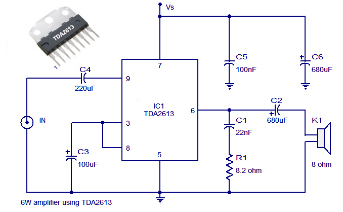


Notes

  • Assemble the circuit on good quality PCB.
  • Supply voltage (Vs) can be anything between 15 to 24V DC.
  • Heat sink is necessary for TDA2613.
  • Do not give more than 24V to TDA2613.
Continue reading[...]

12v to 5v dc dc converter circuit diagram

0 comments
Power supply is needed for all of electronic circuits. Say you have a 12V power supply and you want to use it as a 5V power supply. Then use this 12v to 5v dc-dc converter circuit diagram to convert 12 volt to 5 volt. This DC converter circuit provide 5V, 1Amp at output. Here is the small schematic circuit diagram of 12volt to 5volt converter.

Circuit Diagram of 12VDC to 5VDC converter:


12v
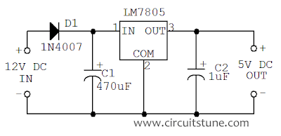
Fig: 12 volt to 5 volt dc converter circuit schematic

This DC-DC converter is based on IC LM7805. The LM 7805 is a 3-terminal fixed output positive voltage regulator IC. The output current of this circuit is up to 1Amp . Use a heat sink with LM7805 to protect the IC from overheating.
Continue reading[...]

Heat Sink Basics

0 comments
As power transistor handle large currents, they always heat up during operation. Since transistor is a temperature dependent device, the heat generated must be dissipated to the surrounding in order to keep the temperature within permissible limits. Generally, the transistor is fixed on a metal sheet (usually aluminum) so that additional heat is transferred to the Aluminum sheet. The metal sheet that serves to dissipate the additional heat from the power transistor is known as heat sink.

heat
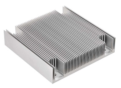
Fig-1:  Heat Sink (Aluminum Sheet)


aluminum
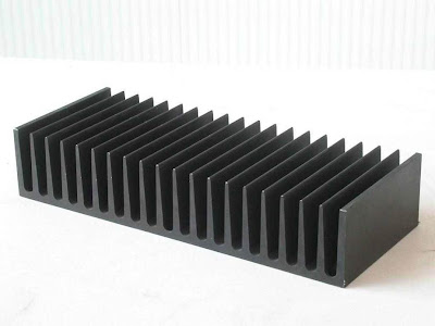
Fig-2: Heat Sink (Aluminum Sheet)


Heat
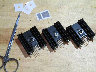
Fig-3: Heat Sink with Transistor/IC

Heat
Fig-4: Heat Sink with Transistor/IC

Most of the within the transistor is produced at the collector junction. The heat sink increases the surface area and allows heat to escape from the collector junction easily. The result is that temperature of the transistor is sufficiently lowered. Thus almost the entire heat in a transistor is produced at the collector-base junction. If the temperature exceeds the permissible limit, this junction is destroyed and the transistor is rendered useless.
Most of power is dissipated at the collector-base junction. This is because collector-base voltage is much greater than the base-emitter voltage, although currents through the two junctions are almost the same.

Heat sink is a direct practical means of combating the undesirable thermal effects e.g. thermal runaway. It may be noted that the ability of any heat sink to transfer heat to the surrounding depends upon its material, volume, area, shape, contact between case and sink and movement of air around the sink. Finned aluminum heat sinks yield the best heat transfer per unit cost. It should be realized that the use of heat sink alone may not be sufficient to prevent thermal runaway under all conditions. In designing a transistor circuit, consideration should also be given to the choice of (i) operating point (ii) ambient temperatures which are likely to be encountered and (iii) the type of transistor e.g. metal case transistors are more readily cooled by conduction than plastic ones. Circuits may also be designed to compensate automatically for temperature changes and thus stabilize the operation of the transistor components.
Continue reading[...]

12 Volt Battery Guardian

0 comments
Dont get caught with a flat battery; this easy-to-build circuit can cut off the power to a 12V fridge or car stereo system if the battery voltages drops below critical level. Electric fridges in vans and 4WDs are a great idea but if you are not careful, they can severely discharge the battery and leave you stranded. Maybe the battery will end up with severe damage as well. The same problem applies if you have a big stereo system and you like to play it without the motor running.


Main features:
  • Cuts power to load (eg, fridge) when battery voltage drops below a preset level.
  • 10A rating.
  • Low power drain.
  • Chirping sound during cut-out.
  • Flashing LED indication during cut-out.
  • Automatically reconnects power when battery recharged.
Operation on 12V is fine when the motor is running and battery charge is maintained but if the fridge is allowed to run for too long when the motor is stopped, it can flatten the battery in a relatively short time. This is where the Battery Guardian comes into play. It monitors the battery voltage and disconnects power to the fridge before the battery becomes too flat to allow the engine to be started again.

Parts layout:PCB layout:
Circuit diagram:
Source: Silicon Chip 6 May 2002
Continue reading[...]
Blog host by Blogger.com & | Supported by you